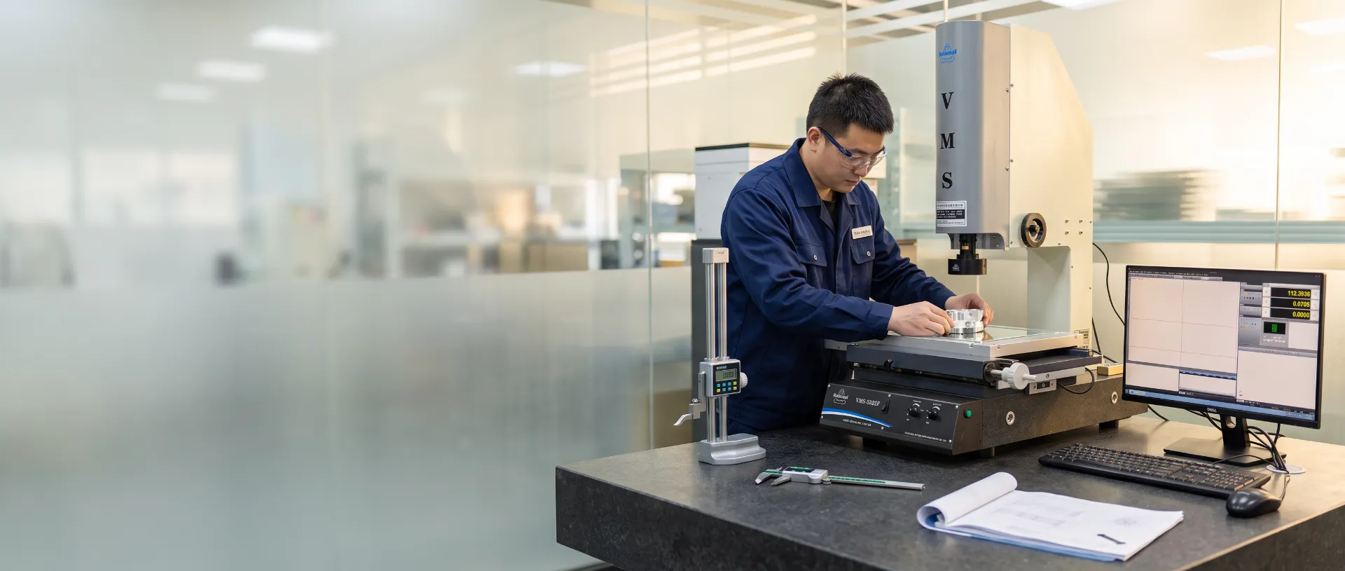
Inspector measuring a CNC machined part on a vision measuring system
HomeQuality
Quality Control · ISO Standards

Every Critical Dimension,
Measured.

From drawing review to final inspection, your parts are checked against the drawing on our vision measuring system and gauges — with inspection reports on request.

  • ±0.01mmTightest tolerance we hold
  • 5Inspection stages per order
  • ISOQuality standards followed
  • 24hQuote with DFM feedback
Quality System

Built Into the Process.Not Checked In at the End.

Our quality management follows ISO standards: every order runs through the same documented steps, from the first look at your drawing to the last part in the box.

  • Prevention First

    Tolerances, datums and finishes are reviewed before a quote goes out, so risks are flagged before any metal is cut.

  • Measured Against Your Drawing

    Critical features are measured and compared with the drawing values — a part passes on numbers, not on looks.

  • Traceable Records

    Material, first-article and final inspection results are recorded per order, and inspection reports are available on request.

  • Continuous Improvement

    Any deviation is traced to its root cause and the process is corrected, so the next batch starts better than the last.

  1. P

    Plan

    Drawing review, DFM feedback and an inspection plan for the critical features.

  2. D

    Do

    Machining with first-article approval and in-process checks at the machine.

  3. C

    Check

    Final inspection on the vision measuring system and gauges, against every drawing tolerance.

  4. A

    Act

    Deviations analysed, root causes corrected and the process updated for the next batch.

ISO Quality cycle
Inspection Equipment

The Right Gaugefor Every Feature.

Profiles, hole positions, diameters, heights, threads and surface finish — each feature is checked with the instrument suited to its tolerance, in our quality room and at the machine.

  • 01Vision Measuring System
  • 02CMM
  • 03Profile Projector
  • 04Height Gauge
  • 05Micrometers & Calipers
  • 06Thread & Pin Gauges
  • 07Roughness Tester
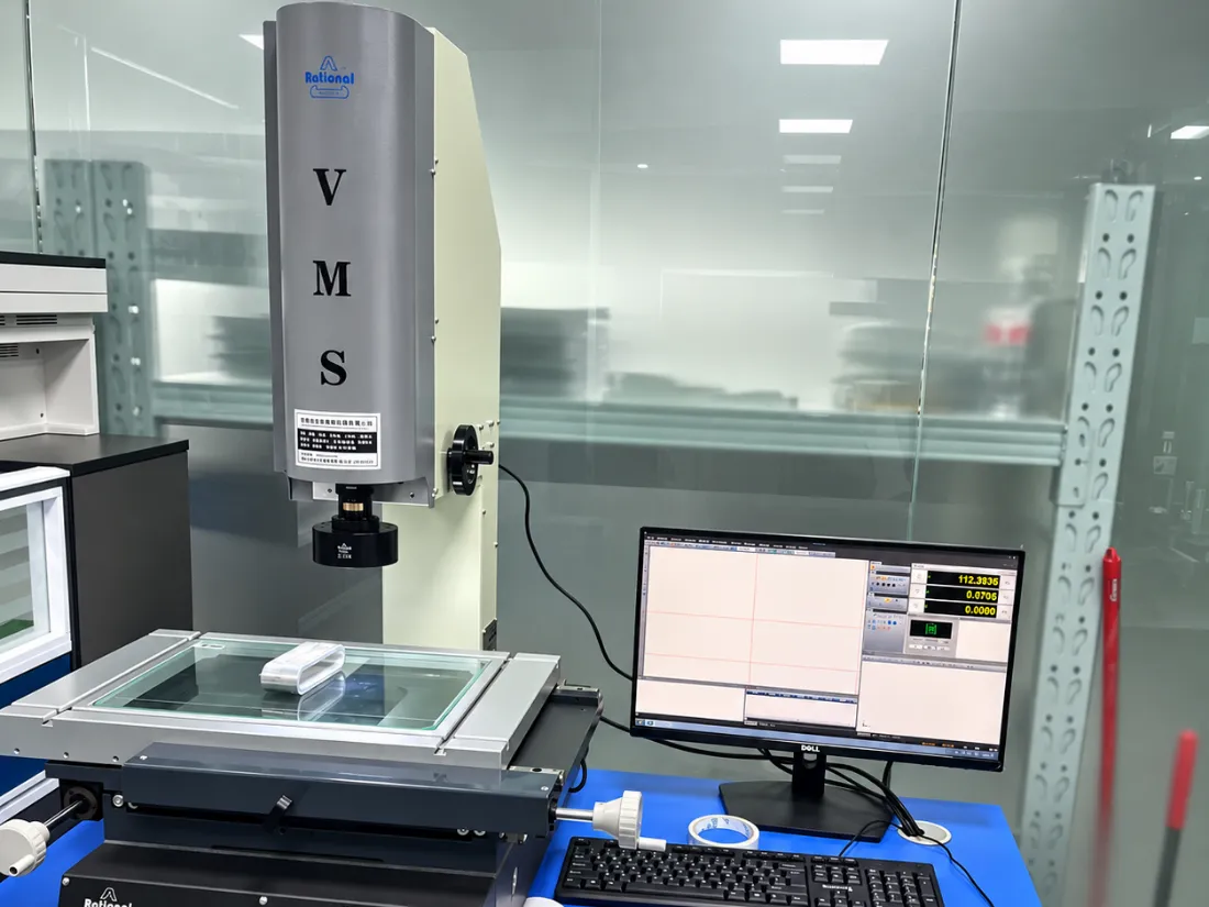
Vision measuring system (VMS) in the HERO Precision quality roomReal photo · Our quality room
Non-contact · Optical

Vision Measuring System (VMS)

The part is imaged through a zoom lens and its edges are detected by software, so profiles, hole positions, diameters and angles are measured without touching the part — ideal for small, thin or delicate features. Final inspection and inspection reports are made on this system.

What it checks

  • 2D profiles and contours
  • Hole diameters and positions
  • Angles, radii and pitches
  • Small and delicate features
First articleFinal inspection & report
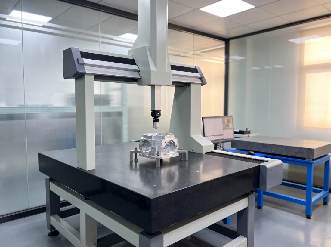
Coordinate measuring machine (CMM) probing a CNC milled aluminum housing
Contact · 3D

Coordinate Measuring Machine (CMM)

A touch probe collects points in X, Y and Z and evaluates the 3D geometry against the datums of your drawing — the instrument of choice for complex milled and 5-axis parts with geometric tolerances.

What it checks

  • 3D positions relative to datums
  • Flatness, parallelism, perpendicularity
  • GD&T callouts on complex parts
  • Multi-face 5-axis geometry
First articleFinal inspection
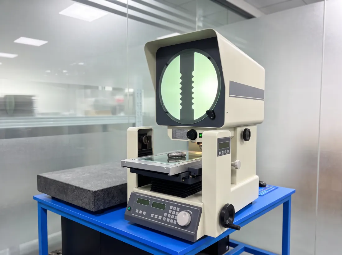
Optical profile projector showing the magnified silhouette of a turned part
Non-contact · Optical

Profile Projector

A magnified silhouette of the part is projected onto a screen and compared with the drawing — a fast, visual way to check the contours of turned parts, radii, chamfers and thread forms.

What it checks

  • Turned profiles and grooves
  • Radii, chamfers and angles
  • Thread forms
  • Edge condition and burrs
First articleIn-process checks
Digital height gauge measuring a step on a machined aluminum block on a granite plate
Contact · Granite plate

Height Gauge

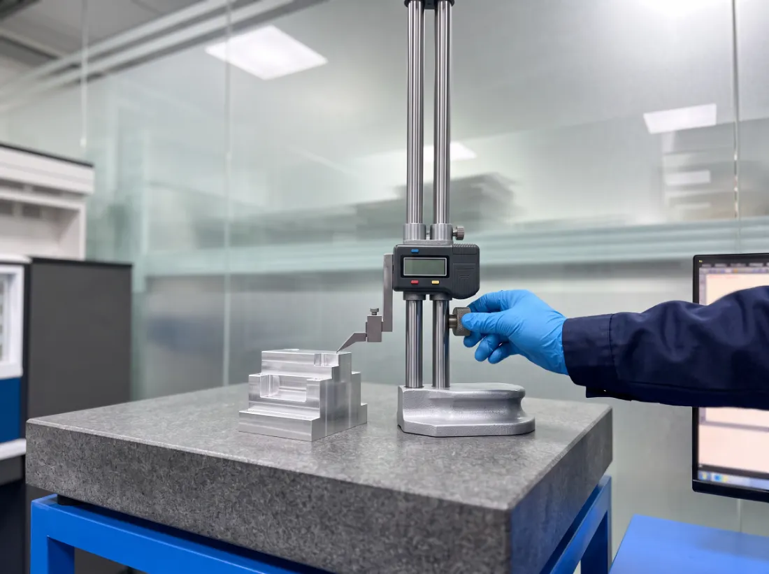
Working from a granite surface plate as the reference, the digital height gauge measures heights, steps and distances, and the centre height of holes and bosses on milled parts.

What it checks

  • Heights and step depths
  • Distances from a reference face
  • Hole and boss centre heights
  • Parallelism of faces
In-process checksFinal inspection
Outside micrometer measuring the diameter of a CNC turned stainless steel shaft
Contact · Hand-held

Micrometers & Calipers

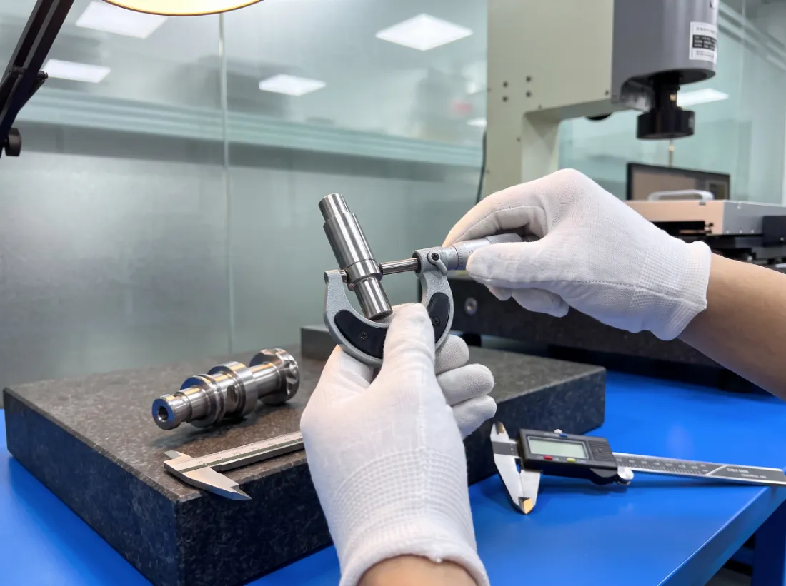
Used at the machine and on the inspection bench: micrometers for tight diameters and thicknesses, calipers for general lengths, widths and depths — the everyday tools of in-process control.

What it checks

  • Outer diameters of turned parts
  • Thicknesses and wall sections
  • Lengths, widths and depths
  • Quick checks during the run
In-process checksFinal inspection
Thread plug gauge in a tapped hole and a set of pin gauges for bore inspection
Go / No-go · Fixed gauges

Thread & Pin Gauges

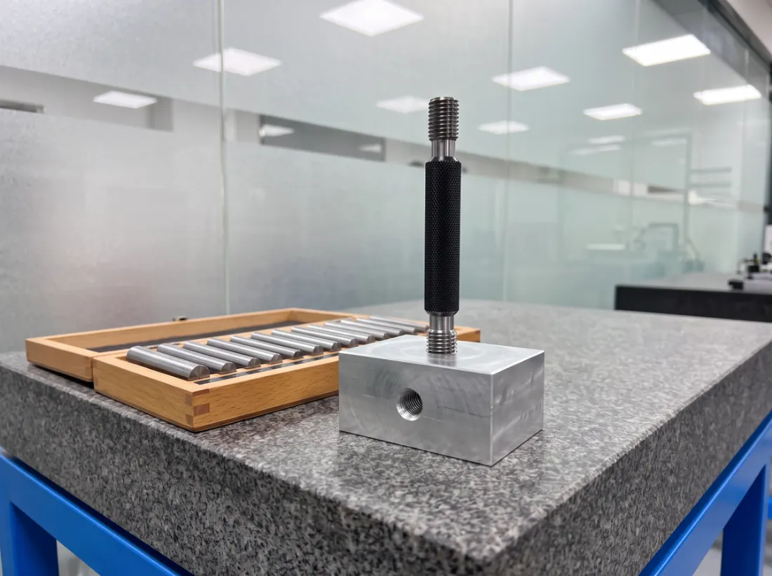
Go / no-go thread plug and ring gauges confirm internal and external threads, and pin gauges check bore sizes and hole fits — fast, objective answers with no reading to interpret.

What it checks

  • Internal threads (plug gauges)
  • External threads (ring gauges)
  • Bore sizes and hole fits
  • Thread depth and engagement
In-process checksFinal inspection
Surface roughness tester stylus measuring Ra on a turned stainless steel shaft
Contact · Stylus

Surface Roughness Tester

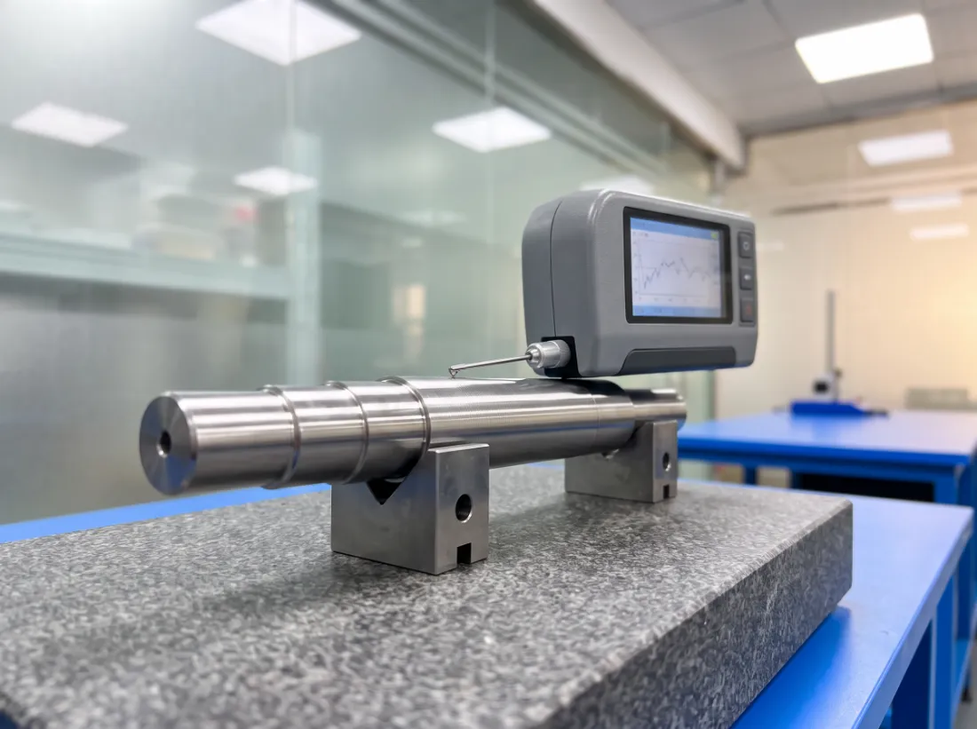
A fine diamond stylus traces the surface and measures its roughness (Ra), so sealing faces, bores and cosmetic surfaces are checked against the finish called out on your drawing.

What it checks

  • Roughness Ra on functional faces
  • Sealing and bearing surfaces
  • Finish before and after polishing
  • Cosmetic surface consistency
Final inspection
Precision & Tolerance

Standard Where It’s Enough.±0.01 mm Where It Counts.

Tight tolerances cost machining time and inspection time. We hold ±0.01 mm on the critical features of your drawing and standard tolerances everywhere else — and tell you in the DFM review where a tolerance can be opened up.

How tight is it?

±0.05mm

Total band 100 µm — about the thickness of a sheet of paper.

±0.01mm

Total band 20 µm — about a quarter of the width of a human hair.

−0.05 −0.01 0 +0.01 +0.05

Deviation from nominal (mm). Each dot = one measured part — illustration.

  • Sheet of paper≈ 100 µm
  • Human hair≈ 70 µm
  • Our ±0.01 mm band20 µm
Feature Standard Tight critical features Checked with
Linear dimensions ±0.05 mm ±0.01 mm VMS, height gauge, calipers
Outer diameters (turned) ±0.05 mm ±0.01 mm Micrometer, VMS
Bores & hole diameters ±0.05 mm ±0.01 mm Pin gauges, VMS, CMM
Hole positions ±0.05 mm ±0.01 mm VMS, CMM
Threads 6H / 6g Class per drawing Thread plug & ring gauges
Surface roughness Ra 3.2 µm Ra 0.8 µm Roughness tester
Untoleranced dimensions ISO 2768-m ISO 2768-f Per drawing

Achievable tolerances depend on material, size and geometry. We confirm them feature by feature in our DFM review, before you place the order.

Check My Tolerances
Inspection Process

Five Checkpoints.From Drawing to Delivery.

Every order passes the same five stages, each with its own checks and records — so a problem is caught where it starts, not at your incoming inspection.

  1. 01

    Drawing Review & DFM

    Before a quote goes out, an engineer reviews tolerances, datums, threads and finishes, and flags features that add cost or risk.

    • Critical dimensions & datums
    • Material & finish callouts
    • Manufacturability risks
    DFM feedback with your quote
  2. 02

    Incoming Material

    Bar, plate and rod are checked on arrival, so only the right grade in the right size reaches the machine.

    • Grade against the order
    • Stock dimensions
    • Surface condition
    Material traced to the batch
  3. 03

    First-Article Inspection

    The first part off the machine is measured in full against the drawing before the batch is released.

    • Every drawing dimension
    • Threads, fits and bores
    • Surface finish
    Batch released on numbers
  4. 04

    In-Process Checks

    Critical features are measured at the machine throughout the run, catching tool wear and drift before they make scrap.

    • Critical features at intervals
    • Tool wear and drift
    • Burrs and visual defects
    Corrections made at the machine
  5. 05

    Final Inspection & Report

    Finished parts are measured on our vision measuring system and gauges, then checked again for appearance before packing.

    • Dimensions to the drawing
    • Appearance and finish
    • Quantity and packing
    Inspection report on request
Certifications

Standards We Work To.Documents on Request.

Our quality system follows ISO standards, with requirements that match the industries we serve — from industrial equipment to medical devices and aerospace.

  • ISO 9001 certification mark
    Quality Management

    ISO 9001

    The framework behind every order: documented procedures, inspection records and continuous improvement.

  • ISO 13485:2016 certification mark
    Medical Devices

    ISO 13485:2016

    Quality management for parts used in medical devices, with traceability and risk-based process control.

  • RoHS compliance mark
    Material Compliance

    RoHS

    Restriction of hazardous substances — compliant materials and finishes for electrical and electronic assemblies.

  • AS9100D certification mark
    Aerospace

    AS9100D

    The aerospace quality standard built on ISO 9001, adding risk management and configuration control.

Need the paperwork? Copies of our current certificates and inspection reports are sent with your quote on request.

Request Documents
Inspection Report

Every Dimension,On Paper.

Inspection reports are available on request. A final inspection report lists the ballooned dimensions of your drawing next to the measured values, the instrument used and a clear pass / fail result.

  • Part name, drawing number and revision, material and finish
  • Characteristic numbers that match the balloons on your drawing
  • Nominal, tolerance and measured value for each sample
  • Instrument used for every feature
  • OK / NG per feature and an overall decision
  • Inspector, date and approval
Ask for a Report With Your Quote
Sample
HERO Precision
Final Inspection Report Shenzhen Hero Precision Co., Ltd
Report No.SAMPLE-0000
Part name
Sample bracket
Drawing / Rev.
DWG-SAMPLE · Rev. A
Material
Aluminum 6061-T6
Finish
Clear anodizing
Lot quantity
500 pcs
Samples
3 pcs measured
No. Characteristic Nominal Tol. #1 #2 #3 Instrument Result
1Overall length120.00±0.05120.02120.01119.99Height gaugeOK
2Width45.00±0.0544.9845.0145.00CaliperOK
3Bore Ø12.000±0.0112.00412.00611.998Pin gaugeOK
4Hole pitch80.000±0.0180.00379.99680.005VMSOK
5Thread M66HGo/NG✓✓✓Thread gaugeOK
6Flatness0.02max.0.0080.0110.009CMMOK
7Roughness Ra (µm)1.6max.0.820.910.86RoughnessOK
Overall resultAccepted
Inspected by
Approved by
Date

Sample layout with illustrative values, in mm. Real reports follow the balloons and tolerances of your drawing.

Get a Quote

Send a drawing.Get a price in 24 hours.

  1. 01

    Upload 2D/3D files

  2. 02

    Quote & DFM feedback in 24 h

  3. 03

    Prototype or first article

  4. 04

    Production, inspection, delivery

    Your files stay confidential and are only used to quote.

    Thank you!

    Your request has been received. Our engineers will reply with a price and DFM feedback within 24 hours.